
Projekt Lavalampe, Teil 1 — Hardware
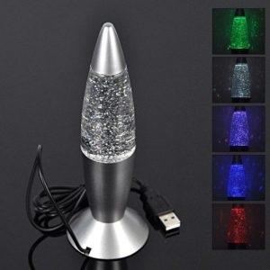 Ich wollte mal wieder etwas mit Elektronik basteln und überlegte, eine Lampe zu bauen, die in verschiedenen Farben leuchtet und die von einem Computer programmiert werden kann. Meine Idee ist, das Ding an den Computer anzuschliessen und den Computer dann verschiedene Zustände durch unterschiedliche Farben anzeigen zu lassen. Beispielsweise soll ein laufender Programmbuild während des Compilierens und Testens blau blinken, und nach Abschluss des Buildvorganges soll die Lampe grün leuchten, wenn alles funktioniert hat, und rot leuchten, wenn es Probleme gab.
Ich habe die nebenstehende Lavalampe gefunden, die mit einer farbigen LED ausgerüstet ist, die von sich aus andauernd die Farbe ändert, und die mit einem USB-Anschlusskabel versehen ist, über das sie Strom von einem Computer erhält.
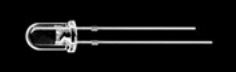 Die eingebaute Farbwechsel-LED ist ein Sondermodell. Sie sieht aus wie eine normale einfarbige LED, hat aber drei LEDs für rot, grün und blau sowie einen Chip, der bei angelegter Speisung automatisch die drei Farben der LED durch alle Regenbogefarben hindurchsteuert in einer zeitlichen Abfolge. Einzelne Farben lassen sich damit nicht gezielt ansteuern. Einzig die Grundfarbe rot lässt sich durch getaktete Speisung erzielen, mehr nicht. Diese LED erfüllt also den von mir gewünschten Zweck nicht.
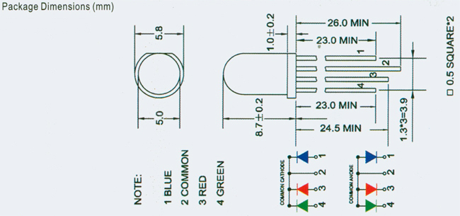 Stattdessen benötige ich eine mehrfarbige LED, deren Grundfarben alle einzeln angesteuert werden können. Solche LEDs kann man kaufen, beispielsweise diese hier mit gemeinsamer Kathode.
Jetzt brauche ich eine Steuerelektronik, die USB-Signale entgegennimmt und somit von einem Computer bedient werden kann, und aufgrund dieser Signale die Farben einer solchen LED steuert. Ein Kumpel wies mich auf den Picaxe Mikrocontroller hin, der einen seriellen Eingang hat und ein paar digitale Ausgänge, mit denen die verschiedenen Farben einer LED gesteuert werden können. Ich kam zu diesem Schaltschema:
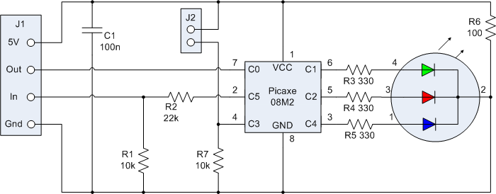
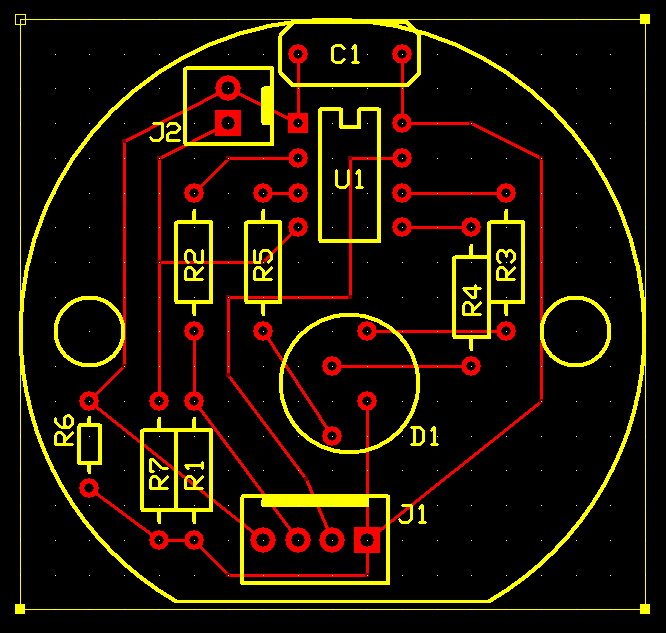 J1 ist der Hauptanschlussstecker mit folgenden Pins:
- +5V
- Serieller Augang
- Serieller Eingang
- 0V
Um den nicht benötigten Eingang C3 doch noch sinnvoll einzusetzen, entschied ich mich, einen Taster vorzusehen, der im Picaxe eine Funktion auslösen kann. Etwa könnte ein festes Farbwechselprogramm ausgelöst werden, oder die LED könnte ein- und ausgeschaltet werden. Der Taster kann an J2 angeschlossen werden.
R6 ist ein Heizwiderstand, der die Lavalampe erwärmen soll, damit das im Wasser befindliche Glitter sich zu bewegen beginnt.
Jetzt brauche ich noch einen USB-zu-Seriell-Adapter. 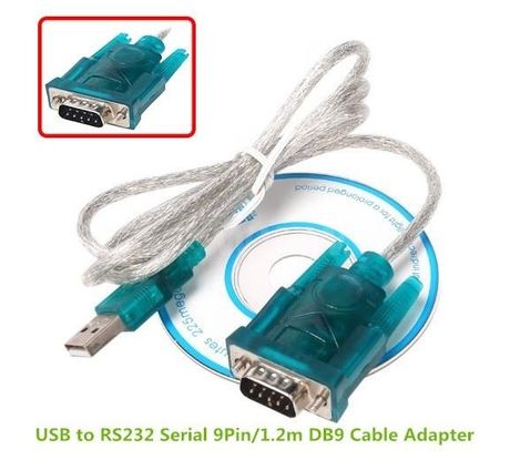 Solche gibt es zu kaufen. Ich habe den hier gekauft, die Kunststoffhülle des dicken Stecker abgezwickt, die darin befindliche Elektronik direkt mit meiner obigen Schaltung verlötet, und das ganze Konstrukt in den Fuss der Lavalampe eingebaut.
Mit diesem Konstrukt hat man ein USB-Gerät, an dem sich am PC ein serieller COM-Port meldet, an den wiederum der Picaxe angeschlossen ist. Dieser kann über die reguläre Picaxe-IDE “Picaxe Editor 6″ programmiert werden. Auf die notwendige Programmierung des Picaxe komme ich in einem späteren Artikel zu sprechen.
Zusammengefasst kann man sagen, dass für meine Projektidee drei Herausforderungen zu meistern sind:
- Die Hardware muss gebaut werden. Diesen Vorgang habe ich hier grob beschrieben und dokumentiert.
- Die Firmware für den Picaxe muss geschrieben werden. Hier handelt es sich um ein Stück Software, das Farbstärken über den USB-Port entgegennimmt und die Dreifarb-LED entsprechend leuchten lässt. Eine solche Firmware habe ich bereits geschrieben.
- Die Software, die aufgrund verschiedener Ereignisse im Computer die gewünschte Leuchtfarbe an den USB-Port ausgibt, steht erst in den Anfängen. Hier befürchte ich auch die grösste Komplexität, bzw. hier kann beliebig viel Aufwand hineingesteckt werden für mehr oder weniger luxuriöse Dinge. Dieser Teil ist womöglich immer irgendwie unfertig. 🙂
